





Length and Spacing of Reinforcements: Key Criteria That Are Often Underestimated
In the design of reinforced earth walls, attention is typically focused on the strength of the reinforcements, the structural capacity, and the strength of the facing. However, there are two parameters that are frequently underestimated during the preliminary design stages and that have a decisive influence on the system’s performance: the length of the reinforcements and their vertical spacing. These parameters not only affect the wall’s internal stability but also the distribution of forces toward the facade and its connections. An inappropriate selection can reduce safety factors, increase facade deformations, and compromise the structure’s long-term performance and durability.
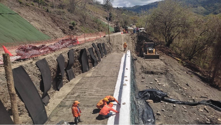
Figure 1. Geogrid Installation FORTGRID UX.
The length of the reinforcements determines the volume of soil that actively participates in the transfer of forces. When the reinforcements are too short, the potential failure surface may extend beyond the reinforced zone, reducing the system’s ability to mobilize the necessary resistance. For this reason, design methodologies establish minimum ratios between the length of the reinforcement and the height of the wall, with the aim of ensuring sufficient anchorage within the stable zone of the soil mass.
In seismic-prone areas, the length of the reinforcing bars becomes even more important, since during a seismic event the wall is subjected to temporary increases in thrust and inertial forces in both the reinforced infill and the facade. These effects generate greater tensile stresses in the reinforcing bars and can displace the potential failure surface inward. As a result, in many cases, longer reinforcing bars than those used under static conditions are required to ensure adequate anchorage behind the failure surface and to maintain the internal and external stability of the system.
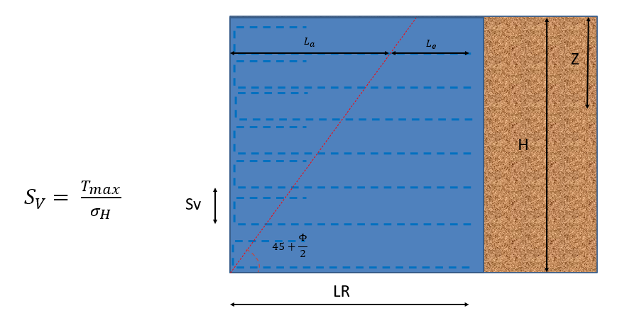
Figure 2. Reinforcement length, pullout.
The height of the wall is one of the most influential factors in this decision. As the structure increases in height, the lateral pressures from the soil and the forces that must be resisted by each layer of reinforcement also increase. A low-rise wall can function adequately with relatively moderate lengths, whereas a tall wall requires a greater span of reinforcement to ensure acceptable levels of stability and deformation control. In road or rail infrastructure projects, where heights are typically significant, this aspect becomes even more critical.
The type of soil used both as reinforced backfill and in the foundation also influences the design. Well-graded granular materials provide more efficient interaction with geogrids or geogrids, allowing for greater friction and adhesion forces. In contrast, fine soils or those with significant moisture content may exhibit less favorable behavior, which often requires increasing the reinforcement lengths or reducing the spacing to compensate for the decrease in load-transfer efficiency.
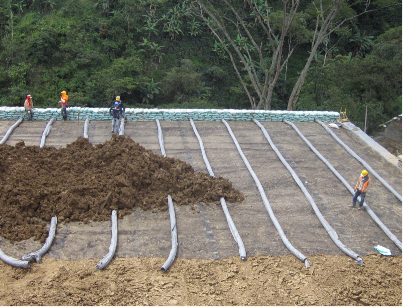
Figure 3. MSR filler material.
Another aspect that is often underestimated is the influence of external loads. Overloads generated by vehicular traffic, nearby buildings, storage piles, or heavy equipment alter the distribution of stresses within the reinforced mass. These forces increase the stresses that the reinforcement must absorb and can shift the potential failure surface inward. As a result, it is common for projects subjected to significant loads to require longer lengths of reinforcement than those used under conventional conditions.
The vertical spacing between reinforcement layers has a direct effect on the distribution of stresses in the soil. When the layers are widely spaced, each must bear a larger portion of the load, increasing individual stresses and local deformations. Conversely, a closer spacing promotes a more uniform transfer of forces and improves the confinement of the fill material. This behavior generally results in smaller displacements at the face and better long-term structural performance.
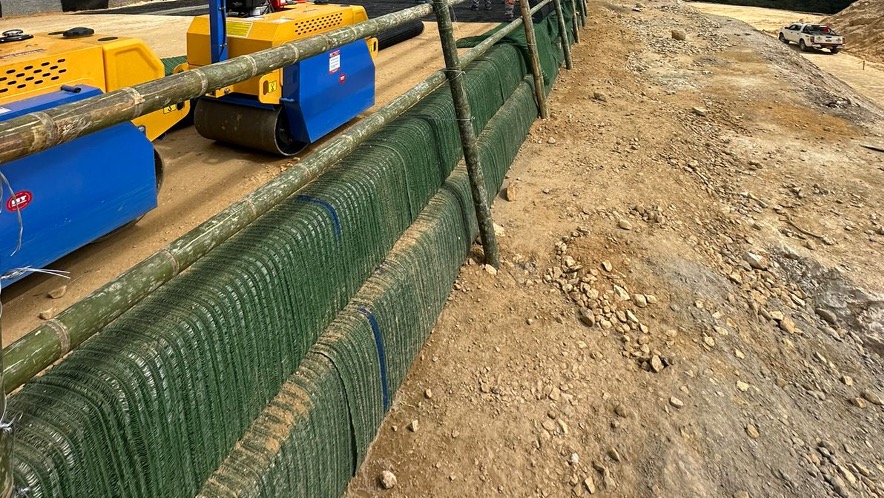
Figure 4. MSR facade with erosion control mat.
From an economic perspective, there is a temptation to increase spacing in order to reduce the number of layers installed. However, these initial savings may be offset by the need to use higher-strength reinforcement or by the occurrence of deformations greater than anticipated. An appropriate balance between spacing and load-bearing capacity usually results in solutions that are more efficient from both a technical and financial standpoint.
The interaction between wall height, geotechnical characteristics, and load conditions requires that each project be analyzed on a case-by-case basis. There are no universal values that can be applied indiscriminately to all situations. Two structures of the same height may require completely different configurations if soil properties, the presence of water, or the loads acting on the wall crown change.
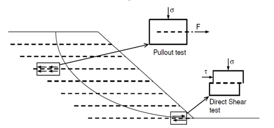
Figure 5. Soil-Geosynthetic Interaction, MSR.
For this reason, the lengths and spacings of the reinforcements should not be considered mere construction parameters. In fact, they are fundamental variables that govern the wall’s stability, durability, and deformation behavior. A rigorous evaluation of these criteria from the early stages of design allows for the optimization of resources, the minimization of risks, and the assurance that the structure will fulfill its function throughout its service life.
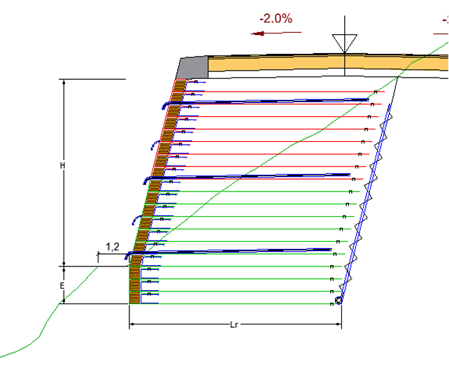
Figure 6. Typical MSR cross-section.
Conclusion
Reinforced soil walls should be understood as systems in which each element works in an integrated manner. The height of the structure, soil properties, seismic risk, and external loads directly influence the required length of the reinforcements and the spacing between layers. Ignoring this relationship can lead to conservative and inefficient designs or, in the worst-case scenario, to performance issues during operation. An approach based on detailed geotechnical and structural analyses is the best tool for achieving safe, durable, and economically optimized solutions.