





MSR Stabilization variant
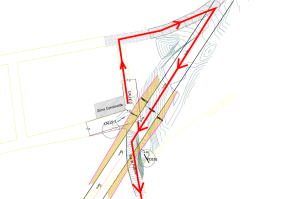
During the construction of a bypass road, an instability problem occurred on one of the slopes adjacent to the road. This geotechnical condition compromised the original layout of the upper road, generating a significant risk for the continuity of vehicular and pedestrian traffic. The loss of MSR stabilization of the slope variant not only affected the structural integrity of the road, but also represented a potential danger to users by increasing the probability of landslides and partial collapse of the terrain.
In order to mitigate these risks and ensure the safety of the road infrastructure, an effective and durable technical solution was designed and implemented. For this purpose, a reinforced soil retaining wall (MSR) was built using high-strength geogrids. This type of structure has proven to be efficient for improving slope stability in areas with complex geotechnical conditions, since it allows the reinforcement to be integrated into the soil itself, increasing its bearing capacity and reducing displacements.
The use of geogrids in the construction of the MSR allowed a more uniform distribution of loads and a favorable interaction between the granular material and the synthetic reinforcements, improving the overall stability of the system. In addition, this construction solution presents advantages in terms of speed of execution, cost-benefit and adaptability to different terrain configurations.
Thanks to the implementation of the reinforced soil wallThe project was able to recover the original layout of the upper road, reestablishing the safety and continuity of both vehicular and pedestrian traffic. The work met the proposed technical objectives and represented an effective response to a common problem in road infrastructure projects located on unstable terrain.
Solution
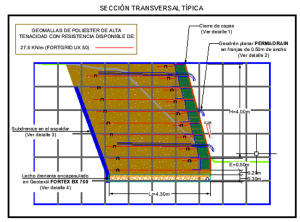
To stabilize the road and mitigate the risk of landslides, the construction of a reinforced soil retaining wall with the following characteristics was chosen:
- Wall height: 4.5 meters
- Separation between reinforcements: 50 cm
- Reinforcement length: 4.3 meters
Materials used
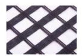
Fortgrid UX 50 uniaxial geogrids
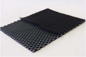
Geodrain Permadrain 450
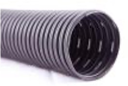
DrainPipe subdrainage pipe wrapped in Fibertex F30G Geotextile
Construction process
- Formation of a drainage bed in granular material for a filter confined with FORTEX geotextile.
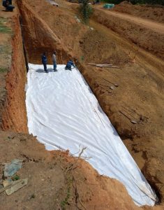
- Installation of a vertical underdrainage system in the trellis with PERMADRAIN geodrainage and reinforcement layers in Geogrid uniaxial FORTGRID UX 50
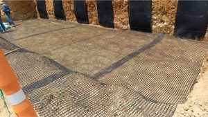
- Horizontal subdrainage system with PERMADRAIN geodrain and confinement at the face with PROPYBAG bags.
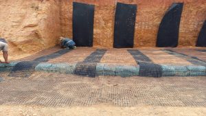
- Compaction of the forming soil
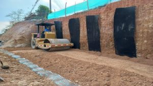
- Compaction process of the forming soil and closing of the layer front with the geogrid.
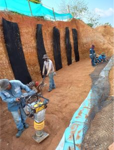
- Formation of the wall facade and confinement of soil layers with PROPYBAG bags.
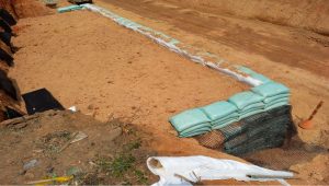
- Provision of forming soil during the construction process
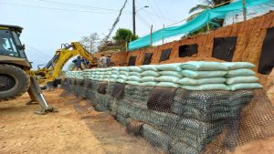
Result
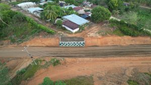
Aerial photograph of the finished structure